API Binding Plans
The API plans presented in this section are developed in accordance with the API 682, 3 revision / API 610, 10 revision standard. This is the standard scheme of the drilling pipes, which are widely used in industry. It is possible to customize these plans to meet the needs of customers.

Description
Inner fluid circulation between the stuffing box and the discharge line, through the connecting channel
Purpose
Heat rejection

Description
It is realized in "blind" oil seal chambers without flushing fluid circulation.
Purpose
Heat rejection

Description
The rinse of the seal from the outlet pipe to the sealing chamber through the diaphragm
Purpose
Heat dissipation, reduction of evaporation

Description
By the API plan 12 the product is circulated between the discharge line and the stuffing box through a coarse filter
Purpose
Heat dissipation, reduction of evaporation

Description
The rinse of the seal from the outlet pipe to the sealing chamber through the diaphragm
Purpose
Heat sink, recirculation

Description
The flushing of the seal from the outlet to the seal chamber via the aperture and flushing the seals from the seal chamber to the inlet through the diaphragm
Purpose
Heat sink, recirculation
Diagram of the system for ensuring the operability of a single seal with the supply of liquid to the oil seal chamber from the pump head.
SINGLE END SEALS

Р1 - is the suction pressure of the pump
Р2 - pressure in the oil seal chamber of the pump
Р2 > Р1, P2 > RATM
Поз. Description
- Control valve
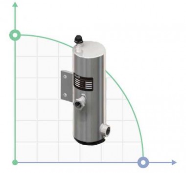
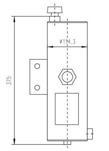
- Refrigerator (installed at an ambient temperature of more than 150...200°C
- "UT" type mechanical seal
- Pump packing chamber
- Pump
- Pump
- Temperature measurement at the exit

Description
Flushing the seal from the outlet pipe to the sealing chamber through the heat exchanger and coarse filter.
Purpose
Cooling
Application
Pumping products with high temperature
Diagram of the system for ensuring the operation of a single seal with an impeller that creates fluid circulation through the stuffing box along an Autonomous circuit.
SINGLE END SEALS

Р1 is the suction pressure of the pump
Р2 - pressure in the oil seal chamber of the pump
Р2 > Р1, P2 > RATM
Item Description
- Control valve
- Refrigerator (installed at an ambient temperature of more than 150...200°C
- "UT" type mechanical seal
- Pump packing chamber
- Pump
- Impeller
- Temperature measurement at the exit

Description
Flushing the seal from the outlet pipe to the sealing chamber via a cyclone separator
Purpose
The removal of heat, removal of solids
Application
Pumping of contaminated product
Diagram of the system for ensuring the operability of a single seal with a "protective" liquid supplied from the outside.
SINGLE END SEALS

Р1 is the suction pressure of the pump
Р2 - pressure in the oil seal chamber of the pump
Р2 > Р1, P2 > RATM
Item Description
- Control valve
- Refrigerator (installed at an ambient temperature of more than 150...200°C
- "UT" type mechanical seal
- Pump packing chamber
- Pump
- Impeller
- Temperature measurement at the exit

Description
Flushing the seal from the outlet pipe to the sealing chamber via a cyclone separator and heat exchanger
Purpose
Cooling and removal of solid fraction
Application
Pumping of high-temperature products containing solid particles

Description
According to API plan 51, barrier coolant is supplied to the seal from an external tank without forced circulation.
Purpose
Duplicate protective mechanical seal
Application
Liquids with high pressure saturated vapors
Diagram of the system for ensuring the operability of the "tandem" type seal with a tank
FOR DOUBLE SEALS OF THE "TANDEM" TYPE»

Creating excess pressure in the tank after it is filled is not required.
If the pressure in the oil seal chamber of the pump is less than the design pressure of the tank (4mpa), the installation of a safety valve on the tank pipelines is not required.
"Tandem" type mechanical seals can be used both with a refrigerator at the pump's working medium temperature up to 400 °C, and without it at the working medium temperature up to 150 °C.
Tohl л = 5...30 °С
Gohl = 0,2…1,5 m3/h
| Item Description | Item Description |
| 1 Gas Reducer | 6 Throttle |
| 2 Pressure Tank | 7 Control valve |
| 3 Tank cooling system | P Pressure measurement |
| 4 Mechanical seal | T Temperature measurement |
| 5 Refrigerator seals | H Level measurement |
Schemes of systems for ensuring the operation of double mechanical seals and the "tandem" type»
FOR DOUBLE SEALS

Diagram of the system for ensuring the operability of a double seal with a tank. The system operates at constant maintenance of the pressure of the shut-off fluid (pressure in the tank) within:
Rzatv = Rzatv + (0,1…0,3) МPа
Gohl = 0,2…1,5 m3/h
At pump working medium temperatures up to 150°C seals are used without a refrigerator, at the temperature of the pumped medium 150...400°C-with a refrigerator.
| Item Description | Item Description |
| 1 Gas Reducer | 6 Throttle |
| 2 Pressure Tank | 7 Control valve |
| 3 Tank cooling system | P Pressure measurement |
| 4 Mechanical seal | T Temperature measurement |
| 5 Refrigerator seals | H Level measurement |

For servicing seals of a group of pumps that perform the same task and are located close to each other, it is possible to use the system diagram shown below.
RSAT = RNS+(0,1…0,3) МPа
Р > Р1 - when fueled with gas
Р < Р1 - when removing the gas pressure
| Item Description |
| 1 Coolant pipe |
| 2 Valve fluid pipeline |
| 3 Gas pipeline (nitrogen, air, etc.) |
| P Pressure measurement |
| H Level measurement |

Description
Circulation of the sealing liquid under high pressure from the diaphragm of the accumulator through the tank
Purpose
Protection against ingress of the pumped product into the environment
Application
Dangerous liquids at high pressure

Description
Circulation of the sealing liquid under high pressure from the piston accumulator through the tank
Purpose
Protection against ingress of the pumped product into the environment
Application
Dangerous liquids, dynamic pressure monitoring system
Schemes of systems for ensuring the operation of double mechanical seals and the "tandem" type»
FOR DOUBLE SEALS

The most commonly used scheme is a system with the supply of shut-off fluid from a separate pipeline with an overpressure m through the seal of the threads.
Rsatv = RNAs + (0,1…0,3) МPа
Твх = 5…30°С, tvx Ј 40°С
G = 0,2…1,0 m3/h
At pump working medium temperatures up to 150°C seals are used without a refrigerator, at the temperature of the pumped medium 150...400°C-with a refrigerator.
| Item Description | Item Description |
| 1 Gas Reducer | 6 Throttle |
| 2 Pressure Tank | 7 Control valve |
| 3 Tank cooling system | P Pressure measurement |
| 4 Mechanical seal | T Temperature measurement |
| 5 Refrigerator seals | H Level measurement |
FOR CONDENSATE PUMPS
Diagram of the system for ensuring the operability of a double seal with liquid supply from the pump head and process pipeline

For condensate pumps, where dry operation of the mechanical seals is not excluded, the guaranteed supply of the shut-off fluid can be carried out according to the following scheme.
RSAT = RNS + (0,1…0,3) МPа
Netzutzot >= 0,2 m cube/h
At pump working medium temperatures up to 150°C seals are used without a refrigerator, at the temperature of the pumped medium 150...400°C-with a refrigerator.
| Item Description | Item Description |
| 1 Mechanical seal | P Pressure measurement |
| 2 Throttle | T Temperature measurement |
| 3 Check valve | G Flow measurement |

Description
In the API 61 plan, all fluid supply channels to the seal are blocked for later use with the API 62 and API 65 plans .
Purpose
The prevention of the deposition of the solid fraction
Application
Pumping of hot hydrocarbons and alkalis

Description
Injection of an external fluid to be used for quenching and flushing/washing. The quench lubricates the seal contact surfaces on the air side, with vapour or water. The flushing/washing operation has a lubricating function.
Objetive
To guarantee seal lubrication, reducing the formation of particles between the contact surfaces due to carbonisation, oxidation or crystallisation.
Applicationі
Horizontal or vertical pumps. Single seal layout. Fluids that crystallise when in contact with the atmosphere or generate solid deposit that block or stick to the seal faces.

Description
API plan 65 allows you to determine the volume of leaks through the mechanical seal. If the friction pair breaks through, the external strapping tank is equipped with an upper-level alarm that will trigger as soon as the liquid level in the tank increases.
Purpose
For cases where the pumped product may condense from the atmospheric side;

Description
In the API 71 plan, all fluid supply channels to the seal are shut off for later use with the shut-off gas.
Purpose
For subsequent application of API 72, API 75, and API 76 plans;

Description
The system flow of a buffer gas at atmospheric pressure
Purpose
Duplicate protective mechanical seal
Purpose
Pumping of hydrocarbon systems, usually used together with the Plan 75 or Plan 76 scheme

Description
High-pressure shut-off gas supply system
Purpose
Protection against ingress of the pumped product into the environment
Purpose
Dangerous liquid

Description
Discharge to the liquid collector and gas recovery system
Purpose
The collection of leaks
Purpose
Leakage of condensate

Description
Discharge to the gas recovery system
Purpose
The collection of leaks
Purpose
Leak of non-condensing gases


